The basic components of a battery energy storage system
This is part one of our new series which introduces the basics of battery energy storage systems (BESS). This first article will be about the components that make a BESS and what they all do.
The battery energy storage system is composed of many components beyond just the batteries. Many power electronics and other systems must be involved for a fully functional BESS. Largely we can consider four major components. These are the batteries, the power electronics, the container, and the control system.
Batteries
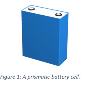
Batteries are the central component of any BESS. The smallest unit of a battery are the battery cells as seen in Figure 1. Multiple cells are put together to form a battery pack. Then multiple packs are arranged together to form a battery rack as seen in Figure 2. One or multiple battery racks are used to make up the total battery capacity of a BESS.
In addition to the batteries there is also the battery management system or BMS that is integrated into the battery packs and rack. The BMS is crucial to the safe operation of the BESS. The BMS handles critical operational data such as battery voltage, temperature, and current. From this data, the BMS calculates how much charge is left on the battery and handles how the battery is charged and discharged.
The BMS generally matches the hierarchy of the battery configuration. So, there will be a battery pack level BMS that handles the operation of a battery pack. The pack level BMS will measure the voltage, temperature, and current of the individual cells of the pack at a given polling rate (such as once per second). It will also handle things such as cell level balancing. This is where individual cells may have slightly different energy capacities and so there is some ability for the pack to control cells that may become overcharged or over-discharged.
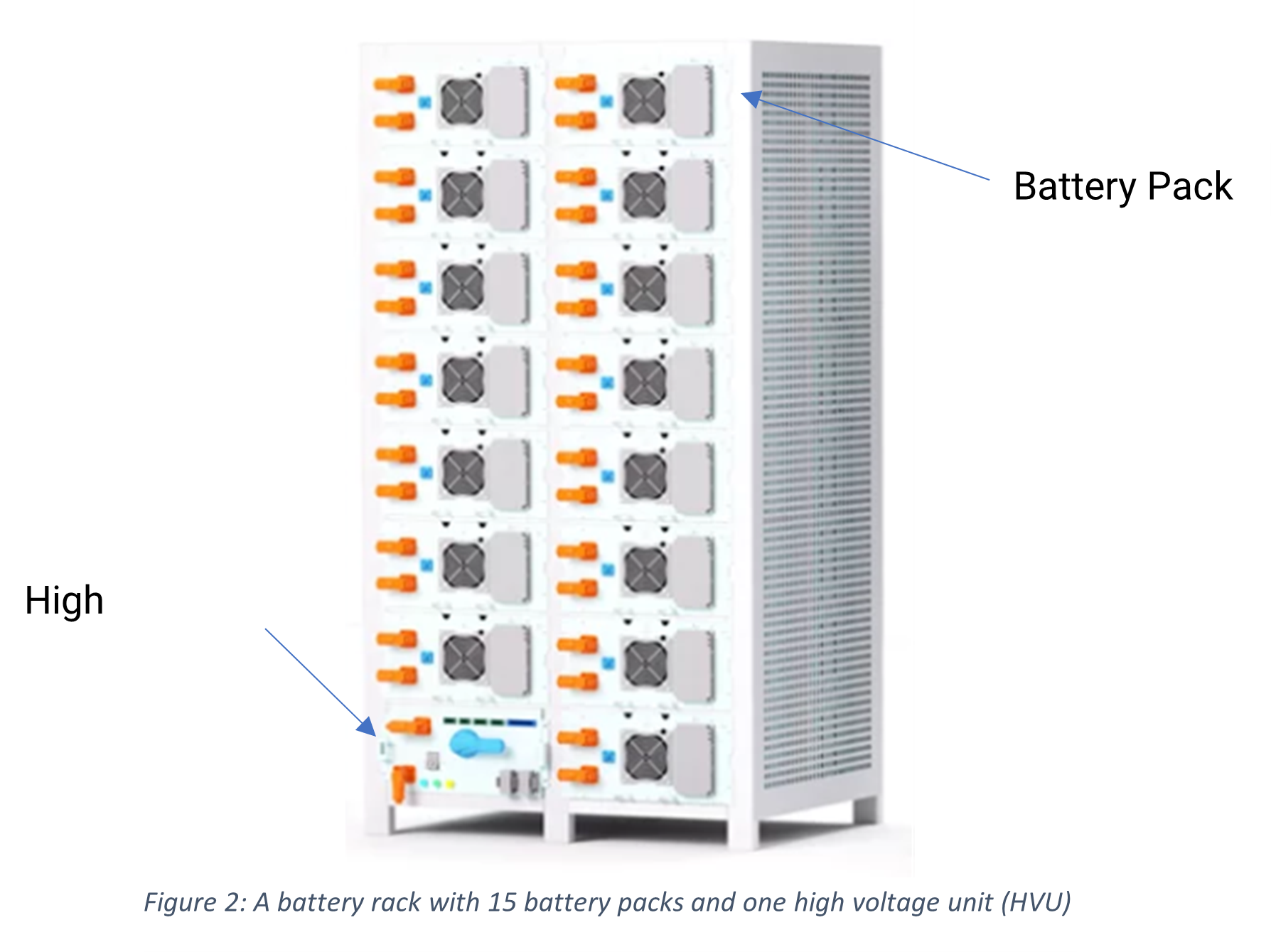
Further up the hierarchy is the rack level BMS. This involves collecting all the individual pack level BMS data and making sure that each pack is properly operating in the scheme of the battery rack. In our battery racks, the rack level BMS is in the high voltage unit. And beyond that is the whole system BMS, where each rack level BMS is collected to ensure safe operation at the system level.
The key pieces of information for the battery component of the BESS are the total energy capacity and the cycle life. Total energy capacity is measured in Watt-hours or Wh with kWh and MWh being commonly used. For a point of reference, according to the U.S. Energy Information Administration the average U.S. household uses 11,000 kWh of energy per year. The other key metric for the battery is cycle life which measures battery decay rate. This is a measure of how many times the battery can charge and discharge before it reaches its end of life (EOL).
There can be some confusion about cycle life as different providers can rate it differently. Some consider EOL to be when the battery capacity has degraded to 80% of its original capacity while some consider it to be 70% of its original capacity. Additionally, some providers are not specific about what constitutes a charge and discharge. For example, battery decay rate is significantly different if the battery is never discharged beyond 50% of its capacity versus a battery that is consistently discharged to 10% of its capacity.
Power Electronics
The power electronics in a BESS are responsible for the connection of the BESS to the grid, load, and distributed energy resources such as solar panels. Batteries and solar panels use DC power, while both the load and the grid use AC power. Thus, the primary role of power electronics is to convert between these two different power systems.
The main power electronic component is the power conversion system or PCS. This is a bi-direction inverter/rectifier device for converting DC to AC to discharge the battery to the AC grid/load, and for converting AC to DC to charge the battery from the AC grid.
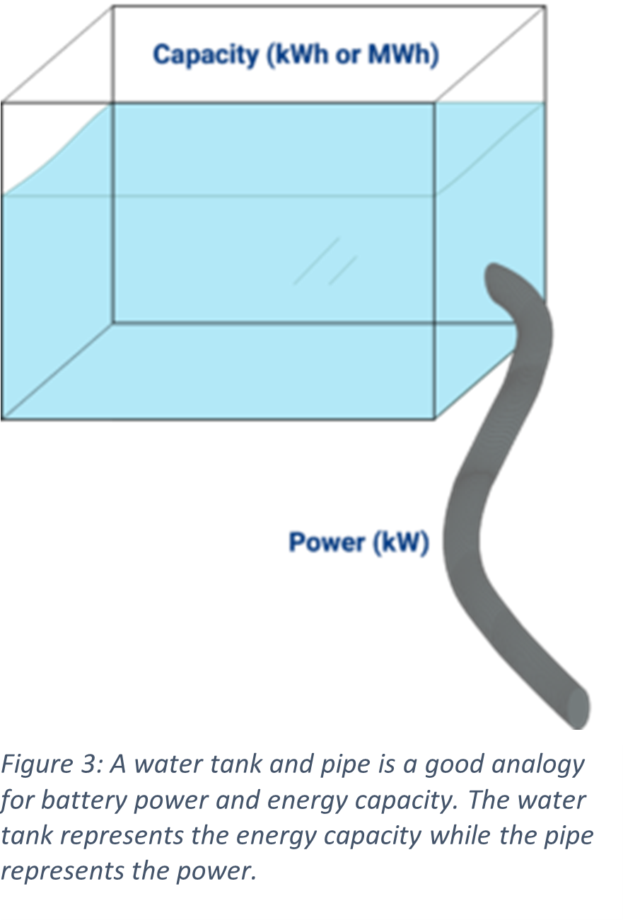
The most important metric for the PCS is the power rating measured usually in kilowatts (kW). This is a measure of how much power can be delivered by and to the battery. For a given BESS, the two critical numbers for its size are the power in kW (of the PCS) and the energy capacity in kWh or MWh (of the battery). One useful analogy is to compare the BESS to a tank of water to understand the key difference between power and capacity. Capacity is the size of the water tank while power is the size of the pipe used to put and take out water from the tank.
Another aspect of the PCS is its ability to work in both on-grid and off-grid environments. When the BESS is connected to the electrical grid and load and the grid is running properly, the PCS operates in grid-following mode. This means that the AC output of the PCS follows the AC frequency of the grid. In off-grid mode, the PCS operates in grid-forming mode. This means that the AC output of the PCS defines the AC frequency.
Additional switching hardware is necessary for the PCS to transition from on-grid and off-grid modes so that when there is a grid-outage the BESS and load can disconnect from the grid and rely on battery power. In comparison, a conventional solar inverter only works in grid-following mode and when there is an electrical grid outage, the solar inverter shuts down. This means that if you have PV panels with no battery and the grid shuts down, you will still have no power.
Another power electronics component that some BESS have is a DC/DC converter. The DC/DC handles the connection of one set of DC connections at a given DC voltage to another set of DC connections at a different DC voltage. In a BESS this is commonly used to connect PV panels to the battery. This is called a DC-coupled PV and battery system. DC-coupled PV turns the battery PCS into what can be considered a hybrid PCS, which now acts as an inverter to both the battery and the PV panels. A proper hybrid PCS and DC/DC also will prevent backflow of power from the battery and grid to the PV panels.
Container
Batteries and their power electronics can be put together inside a single container or cabinet. These containers are usually made from steel and allow the system to be placed outdoors. An outdoor container should have at least either a NEMA 3R rating which means its rated for outdoor usage or an IP54 rating which means protection against dust and water.
Generally, containerized BESS are very easy to install as the container simply needs to be placed on a concrete foundation with the batteries and PCS then installed inside. If the BESS has gotten a UN 3536 certification, then installation is even easier as the batteries can be shipped inside the container itself rather than separately.
Beyond the container itself, there are other components that should be included such as HVAC and fire suppression. HVAC is important to maintain the proper temperature and humidity inside of the container if the ambient outdoor environment is not appropriate. Battery operation is very sensitive to extreme temperatures and humidity, with impacts on performance. Thus, the HVAC is important for efficient battery operation.
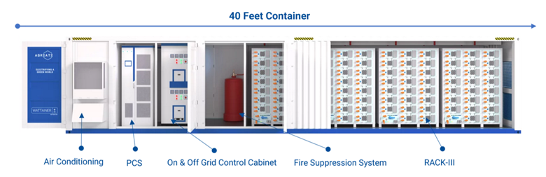
Lastly, every BESS should have a dedicated fire suppression strategy. For containerized systems, this usually represents a combination of smoke, heat, or gas detectors inside the container that can alert to any issues. There should also be fire suppression built into the container such as tanks of fire suppressing chemicals or even an external water connection. Generally, electronics safe fire suppression chemicals such as 3M NOVEC 1230 are preferred to water.
Control Software
The last component of the BESS is the control software. Control software is designed to monitor and control the BESS. One popular control scheme is SCADA or supervisory control and data acquisition which can be integrated into the system in a variety of ways. At minimum a BESS control system should be integrated with the PCS and BMS. Frequently the control scheme will be built into the PCS. It will collect information from the BMS about the battery condition and status which will inform how the BESS should be operated.
The integration with the PCS will allow for control and monitoring of the charging and discharging of the system. Additional sensors and capabilities are also typically available such as control and monitoring of the container temperature through the HVAC.
There can also be options for a variety of human-machine interfaces (HMI). The HMI can be either local or remote depending on the configuration. A local HMI can be as simple as a touchscreen showing BESS information with options for how manage charging and discharge. A remote HMI requires communication systems to be set up usually through an internet connection. Remote HMIs can take the form of web pages which can be accessed via a computer.
Beyond the immediate controls, there can be another level controls such as the energy management system or EMS. The EMS can be an extension of the SCADA system, or it can be its own set of hardware and software the interfaces with the SCADA system. The EMS enables more complex operations of the BESS. For example, power and energy arbitrage from the local utility grid which functionally means buying energy from the grid when it is cheap and storing in the battery and then selling it back to the grid when it is expensive.
Conclusion
Battery energy storage systems are more than just a large collection of batteries. They are a complex array of batteries, electronics and control systems. We hope that this article has shed light on the key components of the BESS.